Cart
Your shopping cart is empty!
It's never too late to make things right :)
Contents:
At first glance, the topic may seem trivial. However, anyone who has encountered the so-called “sparking effect” of connections in a cable junction box—because they loosen or wire ends catch—will certainly not underestimate this problem. The most common cause of fires, contrary to what is usually reported laconically in the media: “The cause of the fire was a short circuit in the electrical network,” is loose or overheated connections of wires or other electrical devices.
The first building installations were made with solid copper conductors. The conductor material, as far as possible, was optimal, but the problem was the insulation, made from a rubberized compound.
At that time, there were usually single lighting points in rooms and a few sockets throughout the building. Individual wires were laid in so-called Bergmann tubes made of rolled strips of sheet metal with tar-impregnated cardboard inside. Components of this system included similarly constructed junction boxes with so-called terminal rings—usually with four brass terminals in the form of threaded sleeves and headless screws. Several solid conductors could be connected under one clamp.
The first insulating material for the ring was porcelain. Later, bakelite began to be used. Similar terminal rings for boxes are still used today, but the threaded sleeves have been replaced by standard spring terminals. The disadvantage of this solution is that the terminals are not insulated, exposing the installer to the risk of electric shock; the number of terminals is limited, usually to four; and the contacts become loose over the service life of the installation.
In addition to terminal rings, screw terminal blocks are still used today. They differ from rings in that the screws are recessed into the insulation, thus protecting personnel from electric shock—although there are also solutions with uninsulated terminals “on top”. They are mostly 12-pole and can be shortened mechanically. In this way, the number of connectable potentials can be easily adjusted to individual needs. However, so-called loose contacts can still occur, and this can lead to failures. Some specialists still connect wires in a junction box by twisting them together (“ramp” twist) or soldering them and then insulating the connection with electrical tape. Although these are safe connections, they are essentially non-separable. Junction boxes, unlike device boxes, were larger—often deeper—to accommodate the necessary switching equipment with sufficient wire reserve. Being separate and closed with a cover, they were prone to being concealed behind furniture, wallpaper, or panels. Then, requiring periodic maintenance (tightening screw terminals), the connections became inaccessible—and therefore prone to failure.
Screw terminal solutions were present in electrical installation boxes until the early 1970s.
This was a real breakthrough in electrical engineering. The previous screw connectors were replaced by so-called Push Wire® terminals with spring clamps made of chrome-nickel steel. A stripped solid conductor is simply inserted into the terminal clamp, and the connection is complete. The wire is removed by twisting it back and forth while pulling it out of the terminal. How simple is that!
The terminals are available as 2-, 3-, 4-, 5-, and 8-conductor versions for conductors with cross-sections of 1.5, 2.5, 4, and 6 mm2. Thus, the product range makes it possible to implement multi-wire systems with solid conductors of all cross-sections used in household installations. The terminal housing is fully insulated, so there is no risk of electric shock when performing service work with the box open.
The current-carrying busbar inside the terminal is made of electrolytic copper. There are no limitations on the number of terminals. We can place as many terminals as will fit in the box. A true revolution in electrical installation technology!
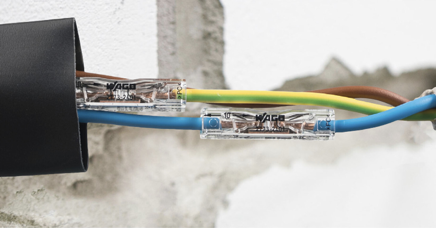
Repairing a damaged cable in a wall using 2773 Inline terminals
In countries that were previously part of the so-called Eastern Bloc, there is a certain inconvenient “electrical” legacy from the past. These are aluminum conductors with cross-sections of 1.5, 2.5, and 4 mm2. They were installed in buildings from the 1950s onward, right up to the end of the communist era. They come with many problems because over time they oxidize, become brittle, and cause many faults. And this is true regardless of whether we are dealing with screw or spring clamps.
Not all types of connecting terminals can be used for connecting aluminum conductors. If it is possible in some cases, it is only after introducing a gel into the conductor entry points that limits oxygen access. Instructions for use and suitable insulating pastes can be obtained from terminal manufacturers.
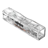
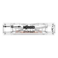
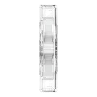
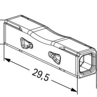
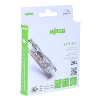
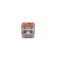
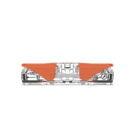
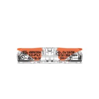
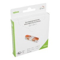
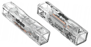
The WAGO 2773 Inline in-line connector is intended for solid conductors.

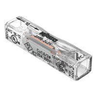
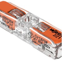
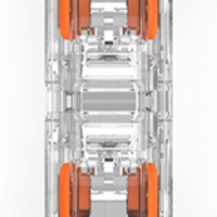
The WAGO in-line connector for all types of conductors – 221 Inline.

Today, as in the past, installation standards still differ from country to country. For example, in most European countries the main conductor used in building installations is solid copper wire. But there are exceptions—for instance, in Italy stranded conductors are used, and in Sweden multi-core conductors. There are also mechanical differences in accessories, especially in the shape and position of the grounding contact in sockets. The development of insulation materials has led to the possibility of laying wires directly in plaster or under it, without the need for installation conduits, which represent a second level of insulation for conductors.
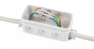
Separate junction boxes, which were often hidden behind furniture, wallpaper, or panels, are also gradually disappearing. All distribution functions are being moved to device boxes. This requires longer conductors and deeper boxes, often with an additional pocket, but they are always accessible for service. Connections between solid single-core conductors and stranded conductors are playing an increasingly important role—for example, when connecting a shutter drive.
Control circuits, which previously were not used in building installations, are becoming important. We connect alarms, phones, intercoms, routers, cameras, etc.
Therefore, conductors with smaller cross-sections are used more and more often. Maintenance-free, safe installation in buildings is becoming increasingly important. All of these requirements are met by an ever-widening range of spring connection terminals, which are becoming more compact, more universal, and easier to use.
Since the late 1970s, terminals have been developed for connecting luminaires, thin telephone wires, stranded conductors, as well as for in-line splicing of conductors. The development of spring connection terminals is shown

Life often forces us to hide a cable junction box behind furniture or, for aesthetic reasons, place it under wallpaper or siding. It can also happen that during decorative work or the installation of additional devices in a building, a cable may be damaged—for example, by drilling through it. Then we will have to connect the conductors in a place that will be inaccessible in the future.
The EN 60998 standard indicates that independent electrical equipment may be used in hard-to-reach places. The German standard VDE 0100-520 states that all connections must be accessible for measurement, testing, and maintenance. Only if the manufacturer clearly indicates that its products do not require these operations may they be installed in hard-to-reach places—for example, embedded in walls. These two conditions—independence of the electrical device and no need for maintenance—are satisfied only by spring terminals, unlike screw terminals which require periodic inspection.
EXPERT OPINION Henryk Ziegler, WAGO
The wires used in building electrical installations in Ukraine are usually solid copper conductors with cross-sections of 1.5, 2.5, or 4 mm2. When such a wire is damaged in a wall or needs to be extended, we usually use screw solutions, or twist the cut conductors together with pliers and insulate the connection with electrical tape. More experienced installers solder the two ends of the wire together. There are also so-called “connecting sleeves” on the market, which are crimped onto the stripped ends of two conductors. They come as bare copper tubes or insulated ones. However, they require an additional tool—a crimping tool. Another problem with connecting sleeves is the limitation to connecting only solid conductors. They are often used only to extend stranded conductors. All of the above in-line splicing methods require space for the operation itself and the use of additional tools.
Today, if we damage a wire in a wall while drilling or want to extend conductors that are too short, we can use the WAGO 2773-2401 Inline terminal. With this terminal, even in the smallest space, solid copper conductors with cross-sections from 0.75 to 4 mm² can be connected quickly and without tools. Thanks to the compact dimensions of this in-line connector (only 30 mm long), installation is possible in confined spaces. And by additionally placing it in heat-shrink tubing, the connection can be plastered into a wall. These terminals do not require maintenance, servicing, or measurements. They enable two conductors to be connected quickly, tool-free, and reliably. A technology that previously took a lot of time, was bulky, and required professional tools will become a thing of the past with the advent of this product.
For those who need to increase the length of a stranded conductor, WAGO offers an in-line connector for all types of conductors – 221 Inline.
It allows conductors with cross-sections from 0.2 to 4 mm2 to be connected.
Henryk Ziegler, WAGO